


Table of contents


No headings in the article.
Whether you know it all or not Networking is complex. Complex architectures are hard to understand right? To make it simpler for everyone, to understand networking, the OSI model was introduced it’s just a conceptual model that was adopted by networking devices and software vendors so that communication is possible seamlessly.
OSI model is the reason devices from different vendors that you have, don’t have a hard time communicating with each other because everyone, participating in this are on one page. Also if the entire communication of such a complex architecture is understood then for any specific problem, troubleshooting becomes easy and if some new requirement came in then it can also be implemented easily.
There exist ‘N’ number of use case of why OSI model? What is the need?
Let’s discuss more on what is OSI (Open System Interconnection) model.
Data is sent out as well as received by your system and the same model is used to visualize its flow of it. For the sake of simplicity, the OSI model is divided into 7 layers and each layer has a defined goal. Each layer works independently without worrying about other layers.
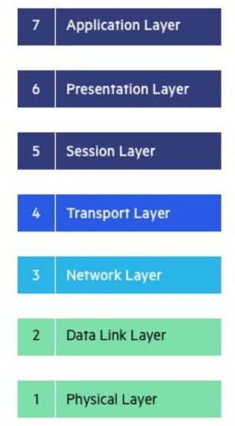
Application:
This layer is closest to the end user, here data is created/consumed using some kind of tool which can be a browser, software, mail client and many more.
eg: HTTP, FTP, SMTP, POP3 …

Presentation:
This layer ensures that data is in understandable format to a machine when data is sent out and to end users when data is received, encoding/decoding, and compression of data are also part of this.
eg: SSL, SSH, JPEG, MPEG…

Session:
This layer ensures and manages a communication channel is kept open/close and functional while data transfer is in progress. This communication channel “sessions” are used between devices for long period communication without interruption.
eg: API’s, Sockets, WinSock…

Transport:
This layer is responsible for the transmission of data, data received from the session layer is broken into smaller chunks and more data is added “Headers” for identification purposes called “segments” and also assembles all the segments turning back into data when received from the network layer. At a time on a system multiple applications/tools may use the internet and this layer identifies data received is for which application using ports. It controls many things like at which rate to send data so that receiving device matches the connection speed, validating received data, requesting again if not received, delivery quality and all.
eg: TCP, UDP…

Network:
This layer is responsible for deciding the path for data transmission and facilitates communication between networks. Segments received from the transport layer is broken into smaller chunks and more data is added for identification purpose called “packets” and also assembles all the packets and turn them back into segments when received from the data Link layer. The best path is discovered by this layer in the physical network for the transmission/routing of packets.
eg: IP, IPSec, ICMP…

Data Link:
This layer is responsible for establishing and terminating connections between connected nodes on the network. Packets received from the network layer is broken into smaller chunks and more data is added for identification purpose called “frames” and also assembles all the frames turning back into packets when received from the physical layer. At this layer, Logical Link Control and Media Access Control works, which identifies network protocols, performs error checking and synchronizes frames, and uses MAC addresses to connect devices and define permissions to transmit and receive data.
eg: ARP, VLAN, Ethernet, Switch

Physical:
This layer is responsible for physical or wireless connections between nodes. Raw data is transmitted in the form of series of 0s and 1s, also takes care of bit rate control.
eg: Cables, Hubs, Fiber

Data flow is bidirectional, at each layer additional information is added such as IP, TCP, Ethernet headers.

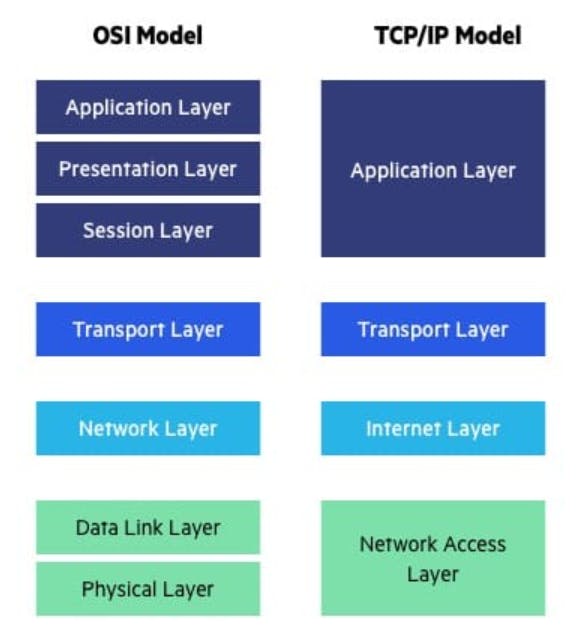
A lot of times OSI model and TCP/IP model is used interchangeably but it is wrong because:
The TCP/IP model is the functional model and OSI model is the conceptual model. What I mean is OSI model is a generic model which can be used to visualize any form of networking whereas TCP/IP model is designed to work with specific network communication and protocols.
Another difference is several layers are collapsed into one.